When you have had no resolution from your internet service provider in Australia regarding your internet service issue such as slow internet speeds, dropouts, service not as described, the Telecommunications Ombudsman (TIO) can assist
The TIO, formed in 1993, offers a free service that acts as a mediator between both parties, in order to ascertain what the client should be able to receive as part of their internet plan, to investigate the issues at hand, and if required make a decision requiring the internet service provider to resolve the issue.
It’s a requirement under the Telecommunications Act for internet service providers in Australia to be a part of the ombudsman’s scheme and co-operate with their processes. This is time and money consuming and also forms publicly accessible statistics, as such it’s no surprise that once a somewhat lackluster response has been had from the internet service provider, a TIO complaint can quickly get the ball moving.
When should you make a complaint to the TIO?
In all situations when you have an problem with your internet service such as slow speed or dropouts, your first point of call is your internet service provider. They need to be aware of your issue in order to be able to rectify it.
Prior contact to your internet service provider with no resolution is a prerequisite before a TIO complaint can be dealt with.
Typically, the position you would be in before you consider submitting a complaint to the TIO regarding your internet service is when you have an issue that :
- Your internet service provider is aware of, and has had the chance to rectify with no success.
- You have not been able to resolve your issue by other means available to you
- You have taken the appropriate steps, and ruled out your issue is not as a result of a problem with in home data cabling, customer premises equipment (CPE), such as routers, laptops, Wifi extenders
Documenting the problem and record keeping
As you need to establish to your internet service provider, and potentially the Telecommunications Ombudsman what issue you are experiencing with their service, keeping logs of when you experience your internet problems are a good idea so long as :
- They are accurate
- Easy to read and understand
- In chronological order, that is from oldest date to most recent
Information you should include would be :
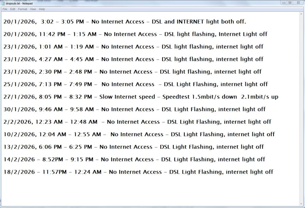
- The date you began to notice the issue, such as when you are browsing and a dropout happened
- The status of the routers Internet / ”Globe” and DSL lights, i.e DSL light ON, Globe light OFF, or flashing
- How long the fault condition is present for, generally until your internet access returns to normal Essentially this is to show that the fault is persistent, recurring, and is causing a significant disruption to your ability to use the internet service
It would also be a good idea to give some time to document various instances, say at least 10 that the issue has occurred, in order to establish that the issue is recurring, and has been happening for a significant period of time. A notepad file on your computer is a suitable method of keeping a log.
If the issue is an unusually slow speed, you can run and record the results of a speedtest using Google Speedtest , or Speedtest by Ookla, both which are free and easily accessible online.
Ruling out customer premises equipment fault
An issue with slow internet speeds or constant disconnections may be caused by your personal equipment, this could be a router, switch, faulty data cabling, computer or internet browser issues. Things you can check are :
- Turn off all devices on the network except the device you normally use, such as switching off other computers, tablets, home theater and streaming equipment
- Check if the issue only happens on Wifi connected devices, if so try go to the same room as the router to see if the issue persists. Connect your laptop to the router directly using a cable instead of using Wifi.
- If you only have a single desktop computer in your household, try borrow a laptop from a friend and test to see if the laptop experiences internet connection issues or slow speed. This may rule out an issue caused by your own personal computer
- Try install a different internet browser, certain plugins can slow down internet browsing speed
- Temporarily disable any cloud backup services, these can run in the background for long periods of time and may cause an unusually slow browsing speed, giving the false impression of a fault elsewhere.
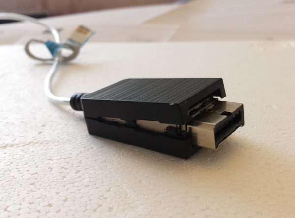
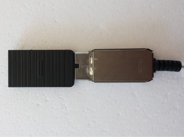
- Try a replacement cable from the router to your wall point or NBN box
Report the issue to your internet service provider
By now you would have a detailed list of when you have been experiencing your internet access issues, as well as completed any checks with your own equipment to rule out any easy to find faults. It now is time to contact your internet service provider
Generally when experiencing an internet speed issue or recurring dropouts, you should first contact your internet service provider. The purpose of this initial contact is
- To explain the issue you are experiencing with the service you pay for
- To allow your internet service provider to investigate the cause of the issue, and provide a solution
It is important to document all of the instances that you have contacted your service provider or have received contact from them, including the date of contact, the nature of the contact, as well as what your service provider has mentioned they will do
After explaining your issue, the questions you should be asking your internet service provider are
- What steps will you be taking to find where the fault lies ?
- Which tests will you run, and what information will those tests reveal ?
- How long will it take for my issue to be resolved ?
Note the answers you receive
If allowable, request an email response summarizing the communication from every phone conversation
It might be worth mentioning, if your premises is currently on a fiber to the node (FTTN) connection, you may find upgrading to fiber to the premises (FTTP) is probably a beneficial step in getting a more reliable internet connection. Ask your service provider if fiber is available at your location.
Your service provider may ask you to carry out checks and repairs to cabling inside your home
Internet connection issues are not always the fault of the service providers end or NBN infrastructure, they can be caused by cabling defects inside your home such as bridge taps, rusted wall outlets, faulty data cabling, rodent damage, internet browser issues or Wifi equipment. You will require the services of an ACMA licensed data cabler to perform these checks and repairs inside your home. If you are requested to carry out repairs, keep in mind the actual cause of the problem may still may lie outside your home.
In the instance of Fiber-to-the-node (FTTN) connections, your cabling installer will aim to run a direct line from the PCD (Premises connection device) or the old grey Telstra box located on the outside wall of the house, directly to one new telecommunications point inside. This bypasses any other old phone outlets that may be daisy chained together.
In the instance of Fiber-to-the-premises (FTTP), your cabling installer may run tests at various points of your home network, such as at the NTD and router, diagnose ethernet cabling such as CAT5 and CAT6 as well as test any Wifi equipment to check where the cause of the issue likely is
Doing any checks and improvements to your home cabling is a step in proving that the fault indeed does lie outside your premises, and good preventative maintenance to give your cabling a clean bill of health.
As we do quite a lot of data cabling in Perth and diagnosis of NBN cabling and internet speed issues, we find that in a significant amount of cases the internet service provider may incorrectly blame the customers cabling. The actual fault in some cases lies outside of the house. However in various instances, customer cabling and equipment issues can cause problems
It’s a good idea to keep detailed notes of all work completed, and ask your cabling contractor for a detailed report on the invoice, and by email of all checks and works carried out. This can include screenshots of any measurements taken, and photos of any defects found and rectified for your records.
Contacting the Telecommunications Industry Ombudsman
Contacting the Telecommunications Ombudsman is one of the the final steps in the resolution process of your internet access issue. The ombudsman will not deal with a matter unless the complainant has contacted their internet service provider first regarding the issue.
It is important to ensure that all steps have been taken prior to making a complaint
- Contacted your internet service provider regarding the issue
- Documented all the instances where the issue occurs
- Ruled out the fault is not caused by your personal computer or Wifi equipment
It is important to read the TIO “What to expect” article here before progressing to make your complaint. A complaint can be made online where you will enter the details of the complaint, where it’s especially important to include :
- All the dates and periods your internet issue has occurred
- The details of your contact and communication with your internet service provider
- The checks that you have carried out on your end
The ombudsman will review your issue and information provided, and may make a decision requiring your internet service provider to fix your issue within 10 days. If required, your internet service provider will liaise with NBN in order to do remediation works on any underground cabling or infrastructure. If the fault cannot be resolved, your service provider may drop you as a customer and you could be eligible for a refund of your service costs. You may have to then consider alternative methods of internet access outside of NBN, such as Telstra, Optus, or Vodafone 4G/5G networks, Fixed wireless from Pentanet and NodeOne, or a Starlink dish installation.